Saturday, August 15, 2015
END OF THE LINE
Life gets in the way of many a dream, forcing us to change course and give up on many of our goals.
In my case, I have spent the last 40 + years photographing and measuring various narrow gauge equipment - locomotives, rolling stock, maintenance-of-way equipment, buildings, all things narrow gauge - starting back in the early seventies while living in Santa Fe.
I became an avid fan of the narrow gauge railroads inching around and through the Rocky Mountains, and along with a few other fellow enthusiasts, became a regular at the Cumbres & Toltec terminus at Chama, New Mexico.
As an NMRA contest modeler, I need some accurate information for my modeling efforts.
One thing I quickly discovered: There were plenty of books full of chit-chat and photos of the narrow gauge world, but nothing - zero, zip, nada - available about measurements, something a one-time modeler like myself needed. There were lots of "scale" models that had hit the market of course, but a really close examination of them would show all manner of inaccuracies. So even the suppliers were fudging on the models whenever no accurate information was available.
Since my job included the use of AutoCad on a regular basis, I was familiar with the program and eventually purchased it for myself to use for my drawings. Since my original purchase, my son, at regular intervals for things like Christmas and birthdays, would upgrade the program to the point I presently have AutoCad 2013 with the latest upgrades.
Needless to say, that is an expense I could not indulge myself to, so I have been eternally grateful that my son has maintained the program for me. And believe me, its not cheap.
I finished a highly accurate collection of drawings of the D&RGW folio six, using copies of the original drawings dated September 1904, 62 pages of the rolling stock in use at that time. It was to be available in either a 8.5 x 11 sized book or a full B-sized 11 x 17 book, drawn in HO and O gauge scales respectively.
However, my sons lawyers - he has several for his company - have warned us that publishing the books could easily generate lawsuits from individuals who may claim to own any and all rights to everything to do with the narrow gauge railroads, photographs, drawings, you name it. Whether they do or not, the resulting legal battle would not be worth the time or money.
Another challenge that arose to completing the detailed erection prints of the locomotives was when my wife was diagnosed with cervical cancer, which she beat, but while in treatment for the cancer she had a massive stroke that wiped out her entire left side. During therapy, she was dropped and broke her back. she is now in a nursing home some thirty miles away, consuming a lot of my daylight hours trying to ensure she is being treated right, something that can be wildly challenging at times. As you can imagine, there is no money left for things like trips to Chama.
So, the drawings have stopped, the trips to Chama for measurements and photographs have stopped. I have tried in vain to get information from those collectors that may indeed have the information I need to finish the locomotives - accurately - but no luck. And at this point, I do not see much chance of a restart.
I have no desire to release drawings that are inaccurate at any point. Although much of what I have completed is quite valid, it is by no means complete.
All I originally wanted back in the 70's was a set of accurate drawings so I could built a model of K36 #484 for an NMRA contest entry. None were available, so I decided to do them myself.
I never dreamed it would take all this time and still not be complete.

Thursday, June 12, 2014
DECISIONS, DECISIONS
I've been working on 3-D component drawings for the K-36 backhead, the latest being the brake valve.

All the K-36 locomotives had essentially the same equipment on the backhead and were probably plumbed the same by Baldwin when the locomotives were manufactured.
However, over the years, as the locos were repaired in various maintenance shops, at different times and by different mechanics, each locomotive took on its own unique arrangement of pipes, tubes and fittings. sometimes keeping closely to the original configurations, other times they pretty much cobbled together anything that would keep the locomotive running, particularity during times of financial stress, something the railroad experienced over and over.
I have photographic records of five of the ten K-36 backheads, and for certain none of the five resemble each other.
What to do? I can't draw up all five versions, too much time would be needed. And those versions probably only existed until the locomotives next visit to the shop. What would be nice would be to depict the backhead as Baldwin originally manufactured them.
I would like to find a photograph or accurate drawing of the "as built" backhead. I've been looking, but so far no luck. I'm sure there are a few photos out there in private collections, but my past experience with owners of these collections indicates that actually being able to borrow and use such a photo is, well... not very likely, and I have neither the time nor resources to go research various State and local libraries and museums for information that may or may not be there.
If I have no luck in finding some reliable information, I will most likely use - from each backhead - what seems to be the most likely and reasonable path and fittings for the plumbing.
This is not a solution I am very happy with, but one that may be necessary if I ever intend to finish this project.
The K-36 brake valve so far. Plumbing problems
off of every port.
All the K-36 locomotives had essentially the same equipment on the backhead and were probably plumbed the same by Baldwin when the locomotives were manufactured.
However, over the years, as the locos were repaired in various maintenance shops, at different times and by different mechanics, each locomotive took on its own unique arrangement of pipes, tubes and fittings. sometimes keeping closely to the original configurations, other times they pretty much cobbled together anything that would keep the locomotive running, particularity during times of financial stress, something the railroad experienced over and over.
I have photographic records of five of the ten K-36 backheads, and for certain none of the five resemble each other.
What to do? I can't draw up all five versions, too much time would be needed. And those versions probably only existed until the locomotives next visit to the shop. What would be nice would be to depict the backhead as Baldwin originally manufactured them.
I would like to find a photograph or accurate drawing of the "as built" backhead. I've been looking, but so far no luck. I'm sure there are a few photos out there in private collections, but my past experience with owners of these collections indicates that actually being able to borrow and use such a photo is, well... not very likely, and I have neither the time nor resources to go research various State and local libraries and museums for information that may or may not be there.
If I have no luck in finding some reliable information, I will most likely use - from each backhead - what seems to be the most likely and reasonable path and fittings for the plumbing.
This is not a solution I am very happy with, but one that may be necessary if I ever intend to finish this project.
Sunday, May 25, 2014
PIECE BY PIECE...
Drawings are now all 3-D, with measurements taken from the completed 2-D engineering drawings.
Each component, part or gadget is separately drawn and then fitted to the master.
Shown below is the Throttle assembly as a separate 3-D drawing.

Mostly finished, the round device is the boiler pressure gauge with no face as of yet.
Neat thing about these drawings is they can be rotated in any axis to view the part from any direction.
That means no cheating on the backside of any view.
I'm thinking that - when the drawings are all done - I might construct a model K-36, maybe 3/4" to the foot.
Won't need new glasses with that scale.
Drawings are now all 3-D, with measurements taken from the completed 2-D engineering drawings.
Each component, part or gadget is separately drawn and then fitted to the master.
Shown below is the Throttle assembly as a separate 3-D drawing.
Mostly finished, the round device is the boiler pressure gauge with no face as of yet.
Neat thing about these drawings is they can be rotated in any axis to view the part from any direction.
That means no cheating on the backside of any view.
I'm thinking that - when the drawings are all done - I might construct a model K-36, maybe 3/4" to the foot.
Won't need new glasses with that scale.
Tuesday, February 25, 2014
SOME NEW STUFF
Things have been hectic to say the least this last year but have settled down to the point I can return to my K-36 drawing effort. (more of a pasttime than an effort)
I purchased a new printer-scanner-plotter, an Epson WF-7520 capable of scanning and printing B size prints. The units were on a closeout sale at one of the office supply outlets for about 20% of the list price. A real bargain, and a great unit.
Below are some "B" sized prints/scans I've been working one lately.

Each component - or sub-assembly - are drawn on separate layers. Most of the layers are turned off in the above print.... brakes, equalizer, etc.


This is all done with AutoCad 2014, a licensed version which was a gift from my son to keep me occupied. A very expensive gift, but quite appreciated.
The K-36 pictorial version is called "Shades of Gray" by AutoCad . When drawing in 3-D, using the "wire frame", the "shades of gray" is a vital viewport when trying to see where everything is located.
Below is a "wireframe", what I usually see when working a drawing.

It's next to impossible to figure out much with a 3-D wireframe.
The top two views are plotted in "hidden" mode, where any lines behind an object are not drawn. Also very handy when figuring our where - and what - things are
I'm working on the firebox and cab now. The backhead is taking a LOT of time and computer memory.
However, my computer was updated with a 2TB Hard drive, and 4G memory.
No problem.
Things have been hectic to say the least this last year but have settled down to the point I can return to my K-36 drawing effort. (more of a pasttime than an effort)
I purchased a new printer-scanner-plotter, an Epson WF-7520 capable of scanning and printing B size prints. The units were on a closeout sale at one of the office supply outlets for about 20% of the list price. A real bargain, and a great unit.
Below are some "B" sized prints/scans I've been working one lately.
Underview of the K-36
Pilot and snowplow top and bottom views
A bit of the K-36 pictorially
This is all done with AutoCad 2014, a licensed version which was a gift from my son to keep me occupied. A very expensive gift, but quite appreciated.
The K-36 pictorial version is called "Shades of Gray" by AutoCad . When drawing in 3-D, using the "wire frame", the "shades of gray" is a vital viewport when trying to see where everything is located.
Below is a "wireframe", what I usually see when working a drawing.
Same as the above pictorial, with several more layers turned off.
It's next to impossible to figure out much with a 3-D wireframe.
The top two views are plotted in "hidden" mode, where any lines behind an object are not drawn. Also very handy when figuring our where - and what - things are
I'm working on the firebox and cab now. The backhead is taking a LOT of time and computer memory.
However, my computer was updated with a 2TB Hard drive, and 4G memory.
No problem.
Sunday, December 16, 2012
READY FOR PUBLISHING, MAYBE

"B" sized pages, most drawings 1/4" scale
Got a proto copy of my book of AutoCad generated drawings of D&RG folio six . The pages are "B" sized, 11 x 17, so almost all the drawings are 1/4" = 1' 0" scale, or "O" gauge.
It's pretty big when opened up, over three feet across.
Included, as bonus drawings, are some locomotive drawings from the first 2-4-0 through the C-19's, a couple of the K-36, locos from the Colorado Southern, the Rio Grande Southern and the Denver, South Park & Pacific.
The hard part is figuring what to do next. Seeing if such a book is even wanted by anyone is step one, and then how to get it published... if warranted.
Even if nobody else wants one, I now have the only book in the world with the greatest concentration of detailed and accurate demensional information on the D&RG ever assembled under one cover.
This all started when I was a contest modeler in the NMRA, Rio Grande Division and badly needed good dimensional details of the models I was doing.
One of my contest models shown below took a couple years to gather enough information to build a reasonably accurate HOn3 scale model.

First place, passenger cars, 1981 RMR NMRA Denver convention.
(left click to enlarge)
Now that I have all manner of information, my eyes are too bad to do any serious modeling.
That's the way it goes.
Saturday, June 09, 2012
MY LACK OF POSTS
I've upgraded from my older version of AutoCad to AutoCad 2013, and it's a bit like picking up a book to read that's in another language... only partially understood.
In the years between versions, autodesk has changed many many features of it's product, so much so it seems a different product.
I'm sure they consider many of the changes as desirable new bells and whistles, but a lot of them just get in the way of creating a drawing up from ground zero.
The programmers at Autodesk - like so many other programmers - still need to lean the basic rule about "If it works, DON'T FIX IT"!
So, as a result, I'm spending many hours re-learning what I once knew and could use proficiently with yet another "all new and improved" update.
It's probably a better package for all the "improvements", but I'll have to learn about them before I can say they actually help. 2013 seems more like 3D Studio than an engineering drawing package.
I'll post a few more postcards to keep things running.
In the years between versions, autodesk has changed many many features of it's product, so much so it seems a different product.
I'm sure they consider many of the changes as desirable new bells and whistles, but a lot of them just get in the way of creating a drawing up from ground zero.
The programmers at Autodesk - like so many other programmers - still need to lean the basic rule about "If it works, DON'T FIX IT"!
So, as a result, I'm spending many hours re-learning what I once knew and could use proficiently with yet another "all new and improved" update.
It's probably a better package for all the "improvements", but I'll have to learn about them before I can say they actually help. 2013 seems more like 3D Studio than an engineering drawing package.
I'll post a few more postcards to keep things running.
Tuesday, January 31, 2012
THE K-36 FRONT END (PART OF IT)

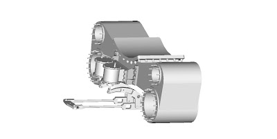
I had decided to 3-D the pilot before tackling the backhead under the assumption that it would be easier. Seems I like to fool myself like that more and more. Turns out getting the necessary details on the construction of the pilot, the truck, the snowplow, pilot beam and the host of other little doo-dads was a real challenge.
I'm presently 3-D'ing the coupler... because I enjoy inflicting pain on myself.
Seriously, none of this has been a walk in the park, but I am getting closer to wrapping this project up.
Once again, this is just another "quickie" render, and several layers are not shown, so the snowplow assembly can be more easily seen.
I had decided to 3-D the pilot before tackling the backhead under the assumption that it would be easier. Seems I like to fool myself like that more and more. Turns out getting the necessary details on the construction of the pilot, the truck, the snowplow, pilot beam and the host of other little doo-dads was a real challenge.
I'm presently 3-D'ing the coupler... because I enjoy inflicting pain on myself.
Seriously, none of this has been a walk in the park, but I am getting closer to wrapping this project up.
Once again, this is just another "quickie" render, and several layers are not shown, so the snowplow assembly can be more easily seen.
Wednesday, January 04, 2012
MORE ADDITIONS

This is - of course - more of the K-36. The picture is a "quickie" render without all the added point lights to improve contrast and shadow.
Those steampipes from the superheater manifold, what with all those twists and turns, were pretty tricky. They're not perfect, but close enough.
The CAD file is getting huge. 3-D files - if they have a decent number of isolines, get big in a hurry.(Isolines determine the smoothness of a curved surface.)
This is - of course - more of the K-36. The picture is a "quickie" render without all the added point lights to improve contrast and shadow.
Those steampipes from the superheater manifold, what with all those twists and turns, were pretty tricky. They're not perfect, but close enough.
The CAD file is getting huge. 3-D files - if they have a decent number of isolines, get big in a hurry.(Isolines determine the smoothness of a curved surface.)
Monday, December 19, 2011
WHERE THE BRAKE CYLINDERS ARE
Something seldom seen are the brake cylinders on the K-36, they being snugly tucked away between the frame members and under the smoke box. They are mounted on a bracket attached to the engine saddle.
As you can see, they are mounted vertically and require a bit of leverage to direct the braking force in the right direction.
By the use of a pretty nifty mechanical design(not shown), the stopping force generated by the two brake cylinders is applied equally to all eight drivers. When I get the rest of the brake system drawing completed and rendered, I'll post it.
Something seldom seen are the brake cylinders on the K-36, they being snugly tucked away between the frame members and under the smoke box. They are mounted on a bracket attached to the engine saddle.
As you can see, they are mounted vertically and require a bit of leverage to direct the braking force in the right direction.
By the use of a pretty nifty mechanical design(not shown), the stopping force generated by the two brake cylinders is applied equally to all eight drivers. When I get the rest of the brake system drawing completed and rendered, I'll post it.
Friday, December 16, 2011

Tuesday, October 18, 2011
FINALLY, A FINISHED ITEM OR THREE
 left click to enlarge
This is a completed drawing of three valve gear components on the K36. This rendered drawing is 3-d and can be rotated to view from any angle. All the dimensions are accurate to .0312, or 1/32nd of an inch. This is a good as it will get.
This link yoke was the most difficult component to draw... dozens of different X,Y,Z coordinates for the UCS to create the proper planes for all those curves.
The rest of the valve gear is there, but on different layers that are turned off.
 left click to enlarge
This is a completed drawing of three valve gear components on the K36. This rendered drawing is 3-d and can be rotated to view from any angle. All the dimensions are accurate to .0312, or 1/32nd of an inch. This is a good as it will get.
This link yoke was the most difficult component to draw... dozens of different X,Y,Z coordinates for the UCS to create the proper planes for all those curves.
The rest of the valve gear is there, but on different layers that are turned off.
Friday, October 07, 2011
TRAMWAYS, INCLINES, INCLINE RAILWAYS
The Mount Lowe Incline, Pacicic electric Railway, California

This card, mailed from South Pasadena, Calif., on Nov 3, 1906, is 105 years old.
The Mount Lowe Incline, Pacicic electric Railway, California

This card, mailed from South Pasadena, Calif., on Nov 3, 1906, is 105 years old.

The Pittsbburgh Incline:

Incline Railway up Lookout Mountain, Chattanooga, Tenn.:
This card was mailed August 8, 1907, from Chattanooga, Tenn.
Price's Hill Incline, Cincinnati, Ohio:
This card was never mailed.
Wednesday, October 05, 2011
TERMINALS FROM THE POST CARD COLLECTION
ATLANTA TERMINAL

Atlanta was once the largest rail crossroads in the south. Travelers could get virtually everywhere quickly and conveniently by rail. Built in 1905, this Terminal was the grand portal to the city. It had two Italianate towers and a huge train shed behind. This structure was torn down in 1970, and Atlanta lost a sizable chunk of its architectural history.
Nowadays days Atlanta’s intercity rail depot is a small former commuter rail station located far north of downtown, adjacent to a 16-lane highway.
DENVER TERMINAL

In 1894, most of the central portion of the original 1881 depot was destroyed by fire. A larger replacement depot in the Romanesque style was built in 1891
In 1912, A new central portion, designed by Denver architects Gove & Walsh, was built in the Beaux-Arts style and opened in 1914.
During its heyday, the station served 80 daily trains operated by six different railroads. Today, one daily Amtrak train runs from Chicago to the the Bay Area and passes through this station.
NASHVILLE TERMINAL

Nashville's terminal opened in 1900 to serve the passenger operations of the eight railroads then providing passenger service to Nashville, Tennessee.
The station reached peak usage during World War II when it was the shipping-out point for tens of thousand of U.S. troops and the site of a USO canteen. The formation of Amtrak in 1971 reduced service to the northbound and southbound Floridian train each day. When this service was discontinued in October 1979, the station was abandoned entirely.
RICHMOND TERMINAL

This station, also known as the Broad Street Station, was built as the southern terminus for the Richmond, Fredericksburg and Potomac Railroad (RF&P) in 1917 in the neoclassical style by the architect John Russell Pope.
The station also served the trains of the Atlantic Coast Line Railroad (ACL), the Norfolk and Western Railway (N&W). Eventually, the Seaboard Air Line Railway (SAL), which had formerly used Richmond's other union station (Main Street Station), switched to Broad Street Station.
Passenger service to the station ceased in 1975. The station is now the home of the Science Museum of Virginia.
SOUTH BOSTON TERMINAL

South Station opened as South Central Station on January 1, 1899. It became the busiest station in the country by 1910. A station on the Atlantic Avenue Elevated served the station from 1901 to 1938 and what is now the Red Line subway was extended from Park Street to South Station in 1913. It's train shed(the world's largest) was razed in a 1930 renovation because of corrosion caused by salt air.
South Station was sold to the Boston Redevelopment Authority (BRA) in 1965. Portions of the station were demolished and the land was used to build the Boston South Postal Annex and the Stone and Webster building.
ATLANTA TERMINAL

Atlanta was once the largest rail crossroads in the south. Travelers could get virtually everywhere quickly and conveniently by rail. Built in 1905, this Terminal was the grand portal to the city. It had two Italianate towers and a huge train shed behind. This structure was torn down in 1970, and Atlanta lost a sizable chunk of its architectural history.
Nowadays days Atlanta’s intercity rail depot is a small former commuter rail station located far north of downtown, adjacent to a 16-lane highway.
DENVER TERMINAL

In 1894, most of the central portion of the original 1881 depot was destroyed by fire. A larger replacement depot in the Romanesque style was built in 1891
In 1912, A new central portion, designed by Denver architects Gove & Walsh, was built in the Beaux-Arts style and opened in 1914.
During its heyday, the station served 80 daily trains operated by six different railroads. Today, one daily Amtrak train runs from Chicago to the the Bay Area and passes through this station.
NASHVILLE TERMINAL

Nashville's terminal opened in 1900 to serve the passenger operations of the eight railroads then providing passenger service to Nashville, Tennessee.
The station reached peak usage during World War II when it was the shipping-out point for tens of thousand of U.S. troops and the site of a USO canteen. The formation of Amtrak in 1971 reduced service to the northbound and southbound Floridian train each day. When this service was discontinued in October 1979, the station was abandoned entirely.
RICHMOND TERMINAL

This station, also known as the Broad Street Station, was built as the southern terminus for the Richmond, Fredericksburg and Potomac Railroad (RF&P) in 1917 in the neoclassical style by the architect John Russell Pope.
The station also served the trains of the Atlantic Coast Line Railroad (ACL), the Norfolk and Western Railway (N&W). Eventually, the Seaboard Air Line Railway (SAL), which had formerly used Richmond's other union station (Main Street Station), switched to Broad Street Station.
Passenger service to the station ceased in 1975. The station is now the home of the Science Museum of Virginia.
SOUTH BOSTON TERMINAL

South Station opened as South Central Station on January 1, 1899. It became the busiest station in the country by 1910. A station on the Atlantic Avenue Elevated served the station from 1901 to 1938 and what is now the Red Line subway was extended from Park Street to South Station in 1913. It's train shed(the world's largest) was razed in a 1930 renovation because of corrosion caused by salt air.
South Station was sold to the Boston Redevelopment Authority (BRA) in 1965. Portions of the station were demolished and the land was used to build the Boston South Postal Annex and the Stone and Webster building.
Friday, September 30, 2011
MAIN FRAME OF THE K-36, CENTER SECTION

This is a wireframe view of my 3-D rendition of the K-36, showing only stuff basically below the running boards and without the rear frame and pilot frame. I turned off the layers for the wheels, axles, counterweights and a few other layers so the print would look something besides a mass of undecipherable black ink.
Working on this particular drawing for more than 30 minutes a stretch is a good way to go blind.
I keep asking myself: "Why am I doing this?"
Beats watching TV all day.

This is a wireframe view of my 3-D rendition of the K-36, showing only stuff basically below the running boards and without the rear frame and pilot frame. I turned off the layers for the wheels, axles, counterweights and a few other layers so the print would look something besides a mass of undecipherable black ink.
Working on this particular drawing for more than 30 minutes a stretch is a good way to go blind.
I keep asking myself: "Why am I doing this?"
Beats watching TV all day.
Tuesday, September 20, 2011
THE NAMED STREAMLINERS
just a few of many:
CHICAGO AND NORTHWESTERN'S "400"

It's main claim to fame was that it sported a new type of shock absorber that provided a smoother and quieter ride. Seems to me that it would be the rail that did that.
THE CHESAPEAKE AND OHIO'S "500"

This was the world's first coal-burning steam turbine-electric locomotive . It was 154 feet, 9 3/4 inches long, including it's water tender, and had a top speed of 100mph. The engine alone weighed 411 1/2 tons.
Why was it named the "500"? Well... that was 20% better than calling it the "400", shown above.
THE ILLINOIS CENTRAL'S "GREEN DIAMOND"

Adjustable coach seats - indirect lighting - complete air-conditioning - ash trays at every seat - radio in every car - stewardess - registered nurse - beautifully appointed lounge car - delicious inexpensive meals - tickets at ordinary fares.
That's what it says on the back of this card.
NO, the headlight was not referred to as the "Green Lantern".
THE CHICAGO MILWAUKEE ST.PAUL AND PACIFIC'S "HIAWATHAS"

"Haiwathas"? Yes, there was more than one. At the time, they were considered as the most popular trains in the world.
ZEPHYRS
For a long time, I thought that there was only one "ZEPHYR" and that it went between Denver and somewhere else, that it was the only ever train made of stainless steel, and that it was the only one with that unique front end. Silly me. The railroads, like any other company, were quick to jump on a popular concept and ride it into the ground.
A few of the many ZEPHYRS below:

Yes, it's the "Denver and somewhere" ZEPHYR of my childhood days.
Then there's the below ZEPHYR that did not even get near Denver: The Chicago, Omaha and Lincoln unit.

But it looked like what a true ZEPHYR should look like.
Then came along the Texas ZEPHYR:

Definitely not a true streamlined stainless steel ZEPHYR, it was an attempt to cash in on the magic and allure of the ZEPHYR legend. Perhaps those cars were stainless steel, but I'll bet some very serious money(up to a maximum of one federal reserve dollar) that those very ordinary A and B unit diesels were most likely just painted silver.
And then there's those strange people back on the East coast that wanted their very own ZEPHYR, but just couldn't abide calling it what everybody else did, so they named their ZEPHYR the "FLYING YANKEE". Heh... Maybe they were secretly wishing for more airplanes.

This ZEPHYR was owned and operated by the Boston & Maine RR.
I suppose I should be a bit more diplomatic when bringing up Texans and Yankees - since my wife was born and raised in Boston - and we both live in Texas now.
As usual, you can left click to enlarge all the photos.
just a few of many:
CHICAGO AND NORTHWESTERN'S "400"

It's main claim to fame was that it sported a new type of shock absorber that provided a smoother and quieter ride. Seems to me that it would be the rail that did that.
THE CHESAPEAKE AND OHIO'S "500"

This was the world's first coal-burning steam turbine-electric locomotive . It was 154 feet, 9 3/4 inches long, including it's water tender, and had a top speed of 100mph. The engine alone weighed 411 1/2 tons.
Why was it named the "500"? Well... that was 20% better than calling it the "400", shown above.
THE ILLINOIS CENTRAL'S "GREEN DIAMOND"

Adjustable coach seats - indirect lighting - complete air-conditioning - ash trays at every seat - radio in every car - stewardess - registered nurse - beautifully appointed lounge car - delicious inexpensive meals - tickets at ordinary fares.
That's what it says on the back of this card.
NO, the headlight was not referred to as the "Green Lantern".
THE CHICAGO MILWAUKEE ST.PAUL AND PACIFIC'S "HIAWATHAS"

"Haiwathas"? Yes, there was more than one. At the time, they were considered as the most popular trains in the world.
ZEPHYRS
For a long time, I thought that there was only one "ZEPHYR" and that it went between Denver and somewhere else, that it was the only ever train made of stainless steel, and that it was the only one with that unique front end. Silly me. The railroads, like any other company, were quick to jump on a popular concept and ride it into the ground.
A few of the many ZEPHYRS below:

Yes, it's the "Denver and somewhere" ZEPHYR of my childhood days.
Then there's the below ZEPHYR that did not even get near Denver: The Chicago, Omaha and Lincoln unit.

But it looked like what a true ZEPHYR should look like.
Then came along the Texas ZEPHYR:

Definitely not a true streamlined stainless steel ZEPHYR, it was an attempt to cash in on the magic and allure of the ZEPHYR legend. Perhaps those cars were stainless steel, but I'll bet some very serious money(up to a maximum of one federal reserve dollar) that those very ordinary A and B unit diesels were most likely just painted silver.
And then there's those strange people back on the East coast that wanted their very own ZEPHYR, but just couldn't abide calling it what everybody else did, so they named their ZEPHYR the "FLYING YANKEE". Heh... Maybe they were secretly wishing for more airplanes.

This ZEPHYR was owned and operated by the Boston & Maine RR.
I suppose I should be a bit more diplomatic when bringing up Texans and Yankees - since my wife was born and raised in Boston - and we both live in Texas now.
As usual, you can left click to enlarge all the photos.
Wednesday, September 07, 2011
R. P. O. CARDS
I'll post one every now and again...
The Albuquerque & Ashfork RPO:

Ash Fork, Arizona. A few miles west of Williams on U.S. 40. Population in 2007: 573, consisting of 353 males, 220 females. Not a good place for bachelors.

A water and fuel stop for the ATSF, it's apparently a place that never suffered growing pains.
As usual, click on the pics to enlarge.
I'll post one every now and again...
The Albuquerque & Ashfork RPO:

Ash Fork, Arizona. A few miles west of Williams on U.S. 40. Population in 2007: 573, consisting of 353 males, 220 females. Not a good place for bachelors.

A water and fuel stop for the ATSF, it's apparently a place that never suffered growing pains.
As usual, click on the pics to enlarge.
Sunday, September 04, 2011

Saturday, September 03, 2011


YEP, THE ZEPHYR WAS IN 1934
Awhile back, I posted a view of some trains at the "Century of Progress Exposition, reposted below:

It prompted this reply from Randy:
Bob, the "Century of Progress" was the 1933/34 world fair held in Chicago, at which the Burlington's Pioneer Zephyr was also introduced. Since your postcard does not have the Zephyr (which was on display during the summer of 1934) I think it's from 1933.
I was recently rummaging through the post card collection and sure enough, there was a card with the Zephyr shown and dated as 1934:

It takes hours to go though the collection just once, so it's not surprising that I missed this card earlier.
I have often thought to index and organize all the cards, but I don't think I have enough time left to to that on top of the other things I'm trying to finish up.
Truthfully, I'm just to lazy to do it.
Awhile back, I posted a view of some trains at the "Century of Progress Exposition, reposted below:

It prompted this reply from Randy:
Bob, the "Century of Progress" was the 1933/34 world fair held in Chicago, at which the Burlington's Pioneer Zephyr was also introduced. Since your postcard does not have the Zephyr (which was on display during the summer of 1934) I think it's from 1933.
I was recently rummaging through the post card collection and sure enough, there was a card with the Zephyr shown and dated as 1934:

It takes hours to go though the collection just once, so it's not surprising that I missed this card earlier.
I have often thought to index and organize all the cards, but I don't think I have enough time left to to that on top of the other things I'm trying to finish up.
Truthfully, I'm just to lazy to do it.
Thursday, September 01, 2011
MORE ADDED
I've added more to the backhead while at the same time some pipes and fittings have been moved a bit to aid visualization of how and where things are going.
After looking over a lot of my notes and photos of various K-36's, I'm not a bit concerned if what I show is not like any particular locomotive. Seems all of the locos were plumbed any old way handy. My only concern at this point is to make certain (as possible) that the connections are correct.
The backhead so far:
 left click to enlarge
I have now positioned it in reference to the cab and frame since many of the items to be added are cab or floor mounted, such as the now added Johnson Bar.
There are still lots of pipes and outlets going nowhere, and the throttle lever is just an outline for position.
The side elevations are coming along... Although a bit slower.
I've added more to the backhead while at the same time some pipes and fittings have been moved a bit to aid visualization of how and where things are going.
After looking over a lot of my notes and photos of various K-36's, I'm not a bit concerned if what I show is not like any particular locomotive. Seems all of the locos were plumbed any old way handy. My only concern at this point is to make certain (as possible) that the connections are correct.
The backhead so far:
 left click to enlarge
I have now positioned it in reference to the cab and frame since many of the items to be added are cab or floor mounted, such as the now added Johnson Bar.
There are still lots of pipes and outlets going nowhere, and the throttle lever is just an outline for position.
The side elevations are coming along... Although a bit slower.
Subscribe to:
Posts (Atom)